Anova Gage R
This post will focus on how the variance components are calculated for a crossed Gage R&R using the ANOVA. Gage R&R: How are the Variance Components Calculated? Dec 17, 2013 - 9 min - Uploaded by Advance Innovation GroupThis video will help you understand the Gage R&R test which needs to be conducted to check.
Use the ANOVA table to identify which sources of variability are significant. The ANOVA table includes the following terms in the Source column:.
Anova Gage R&r Excel

Part: The variation that is from the parts. Operator: The variation that is from the operators. Operator.Part: The variation that is from the operator and part interaction.
An interaction exists when an operator measures different parts differently. Error or repeatability: The variation that is not explained by part, operator, or the operator and part interaction.
Use the variance components (VarComp) and%Contribution to assess the variation for each source of measurement error. The sources are as follows:.
Total Gage R&R: The sum of the repeatability and the reproducibility variance components. Repeatability: The variability in measurements when the same operator measures the same part multiple times. Reproducibility: The variability in measurements when different operators measure the same part. Part-to-Part: The variability in measurements due to different parts. Ideally, very little of the variability should be due to repeatability and reproducibility. Shri durga saptashati path mp3 free download. Differences between parts (Part-to-Part) should account for most of the variability.
Anova Gauge R&r
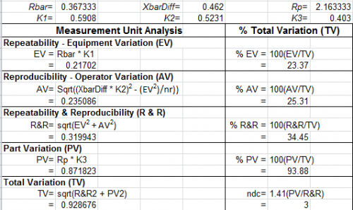
Variance Components%Contribution Source VarComp (of VarComp) Total Gage R&R 0.0020816 6.82 Repeatability 0.0011541 3.78 Reproducibility 0.0009275 3.04 Part-To-Part 0.0284585 93.18 Total Variation 0.0305401 100.00 Key Results: VarComp,%Contribution The%Contribution for part-to-part variation is 93.68%. Minitab divides the part-to-part variance component value, 0.0308455, by the total variation, 0.0329271, and multiplies by 100%. When the%Contribution from part-to-part variation is high, the measurement system can reliably distinguish between parts. Gage Evaluation Study Var%Study Var%Tolerance Source StdDev (SD) (6 × SD) (%SV) (SV/Toler) Total Gage R&R 0.045625 0.27375 26.11 27.37 Repeatability 0.033972 0.20383 19.44 20.38 Reproducibility 0.030455 0.18273 17.43 18.27 Part-To-Part 0.168696 1.01218 96.53 101.22 Total Variation 0.174757 1.04854 100.00 104.85 Historical standard deviation is used to calculate some values for StdDev, Study Var, and%Study Var.
Values for%Process are not displayed because they are identical to values for%Study Var. Key Results:%Study Var Use the percent study variation (%Study Var) to compare the measurement system variation to the total variation.

The%Study Var uses the process variation, as defined by 6 times the process standard deviation. Minitab displays the%Tolerance column when you enter a tolerance value, and Minitab displays the%Process column when you enter a historical standard deviation.
According to AIAG guidelines, if the measurement system variation is less than 10% of the process variation, then the measurement system is acceptable. Because the%Study Var, the%Tolerance, and the%Process are all greater than 10%, the measurement system might need improvement. For more information, go to. The gage R&R graphs provide information about the measurement system. Components of variation graph Shows whether the largest of component of variation is part-to-part variation.
In an acceptable measurement system, the largest component of variation is part-to-part variation. R chart by operator Shows whether any points fall above the upper control limit. If the operators measure consistently, the points will fall within the control limits. Xbar chart by operator Shows whether most points fall beyond the control limits.
The parts that you choose for a gage R&R study should represent the typical part-to-part variability. Thus, you should expect more variation between part averages, and the graph should show that most points fall beyond the control limits. Measurements by part graph Shows whether multiple measurements for each part are close together. Multiple measurements for each part that are close together indicate small variation between the measurements of the same part. Measurements by operator graph Shows whether differences between operators are small compared to the differences between parts. A straight horizontal line across operators indicates that the mean measurements for each operator are similar. Ideally, the measurements for each operator vary an equal amount.

The operator.part interaction graph Shows whether the lines that connect the measurements from each operator are similar or whether the lines cross each other. Lines that are coincident indicate that the operators measure similarly. Lines that are not parallel or that cross indicate that an operator's ability to measure a part consistently depends on which part is being measured. A line that is consistently higher or lower than the others indicates that an operator adds bias to the measurement by consistently measuring high or low.